


Pump Design
Gear Design
Diverse Applications
Our pumps are used for a wide variety of applications, including cylinder filling, automotive fueling, bulk transfer, vaporizers, high-pressure burners, and truck applications.
High Life Expectancy
Balanced internal loading, only available with a Smith 3-gear pump, creates high efficiency and low energy drive requirement when compared with other positive displacement designs.
The point contact and free-floating features of the gear set minimizes constant casing and end disc contact which may create wear and internal slippage in other positive displacement pump designs..
How Does Balanced-Loading in the Smith 3-Gear Pump Work?
- Liquid first enters the inlet of the pump, shown as blue in the upper left corner of the pump main housing. It is also directed within the pump to the bottom right port, also shown as blue.
- As the drive gear in the center rotates in a counterclockwise direction, the low pressure blue liquid is directed into the spaces between the gear teeth and transferred to the red ports, as shown. The velocity of the liquid entering the gear teeth spaces is carefully matched with the speed of the gear set to minimize changes in velocity and directional changes of the liquid, thus minimizing the pressure drop in the pump. Gear pockets are designed to insure a pressure gradient is present around the outside diameter of the idler gears to suppress cavitation and maximize the transfer rate of the pump.
- It is the design and efficiency of the non-contacting side of the gear teeth (in the Red Zones) that largely determines the ability of the pump to develop pressure. Permissible wear on the leading side of the gear teeth does not compromise this performance characteristic of the Smith 3-gear pump. The red ports are also integrated within the pump (high pressure).
- It is important from a loading standpoint that the drive gear is exposed to a neutral load, eliminating the necessity for another ball bearing to support the other end of the drive shaft (which would also add another mechanical seal). Given that the schematic uses color to indicate pressure, the symmetric colors surrounding the drive gear illustrate that the drive gear is balanced.
- As high pressure develops in the red ports, liquid maintains velocity and flows out of the pump through the outlet port shown as red in the upper right corner.
- Secondary gear housings can be added to the main housing shown and are internally ported to match those of the main housing. The addition of a secondary gear housing is not to boost the pressure capability of the pump, but rather to increase the volumetric flow rate of the pump.
High Efficiency
Designed for superior performance, minimal slippage, and ease of maintenance.
Can be replaced without taking the mechanical shaft seal apart.
Mechanical Shaft Seal
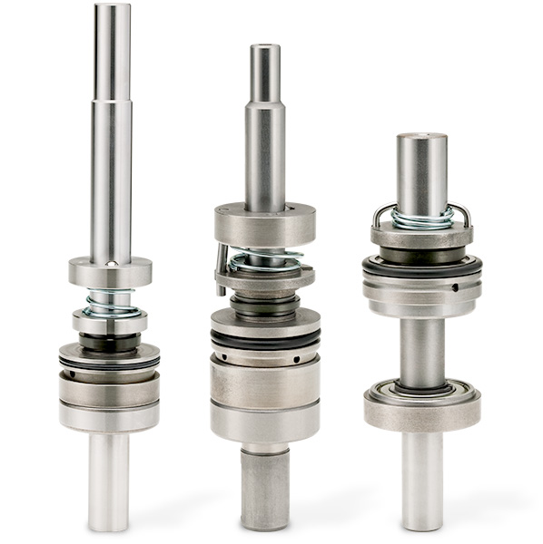
State-of-the-Art
Is an integral part of the pump drive shaft.
Allows the seal ring to rotate at half the shaft speed, leading to increased seal life.
The SUPERSEAL™ option eliminates carbon graphite in favor of a self-repairing thermoplastic intermediary seal ring that continually laps itself while the pump is in operation. Only Smith offers this advanced mechanical seal design.
Mechanical Seal Demonstration Video
Increased safety, ease of maintenance, and state-of-the-art design are just some of the benefits of our mechanical seal.