
World’s First Automated Construction Assembly Line-The Mechanical Marvel
A series of articles outlining the engineering work of Reuben Stanley Smith, founder of Smith Precision Products Company, will be posted this year to highlight the 75th anniversary of the Company (1938-2013). Following is the second article posted this year. Previously posted articles can be accessed by searching Recent News Posts or News Archives.
World’s First Automated Construction Assembly Line-The Mechanical Marvel
The founder of Smith Precision Products Company, Reuben Stanley Smith, was one of several engineers responsible for the design and development of the incredible Mechanical Marvel, while employed by the A.O. Smith Corporation as its Chief Engineer. This article highlights a major American engineering achievement that was honored as a National Historic Mechanical Engineering Landmark by the ASME.
In The Beginning
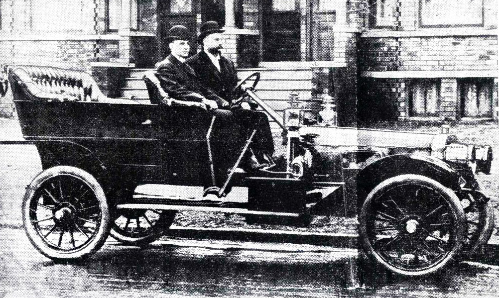
The founder of the A.O. Smith Company, Arthur Oliver Smith (1859-1913), perfected a way to manufacture automobile frames by pressing them from steel. They were much lighter in weight and stronger than the I-beam constructed steel type. His company began making automobile frames around 1904. As the years progressed, however, keeping up with the demand from the growing automobile industry was becoming an almost insurmountable challenge. Even though the company was manufacturing thousands of automobile and truck frames every year, increasing production was difficult and very labor intensive.
By 1916, the annual automobile production in the United States was approximately 1.5 million. This was at a time when the U.S. severed relations with Germany after the sinking of the Lusitania in May, 1915, and declared war on April 6, 1917. On November 11, 1918, the war was over and those manufacturing companies in the States involved with the war effort could refocus on core product lines. The A.O. Smith Corporation was no exception.
The Mechanical Marvel is Born
At the end of 1916, Reuben Stanley Smith, Chief Engineer of the A.O. Smith Corporation, received a directive from his first cousin and President of the company, L.R. Smith (son of A.O. Smith), to develop a process that would not only allow for a vast increase in the number of automobile frames that could be manufactured, but to automate the process to a level never before seen in those times. L.R. Smith’s vision was to produce millions of frames, not thousands. Reuben and his staff were ready for the challenge. His career at the A.O. Smith Corporation was exemplary as he previously developed the electrically heated steering wheel, ball bearings, a pressed-steel automobile wheel, the Smith Milwaukee Motor Truck, the Smith Motor Wheel, and paper coated welding rod and arc welding advancements (See Family Legacy Timeline, Reuben Stanley Smith Patents, 1948).
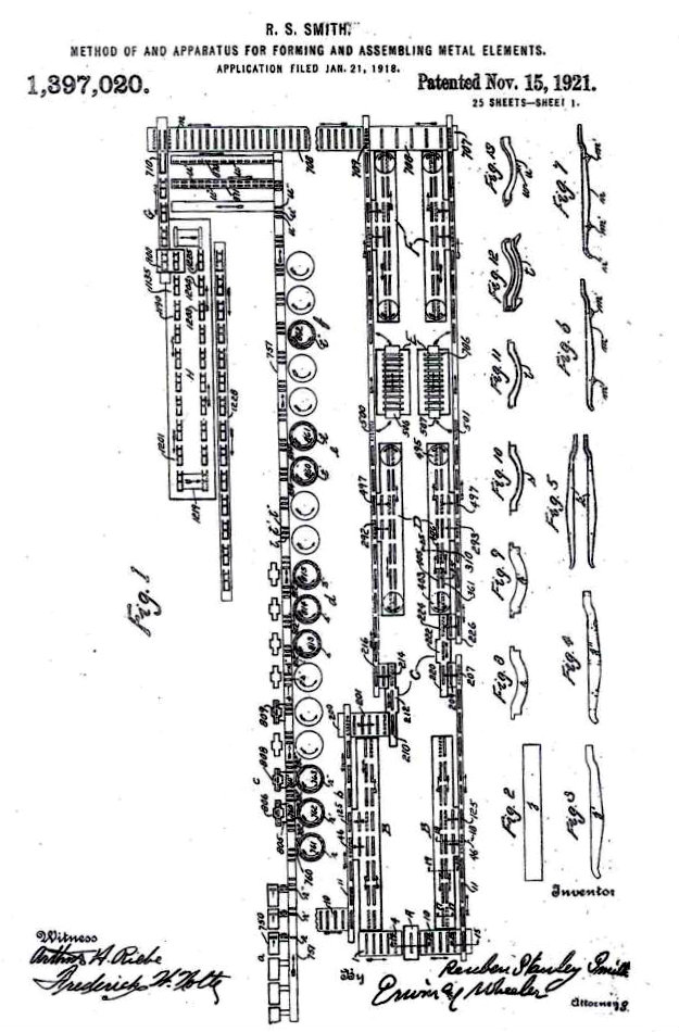
Working up through the end of 1917 during some very trying times, a design was finally agreed upon and on January 21, 1918, a patent application was filed. It was issued to Reuben on November 15, 1921, as Patent Number 1,397,020 and immediately assigned to the Company as were most of his patents. It was entitled “Method Of And Apparatus For Forming And Assembling Metal Elements.” It would later be dubbed the Mechanical Marvel.
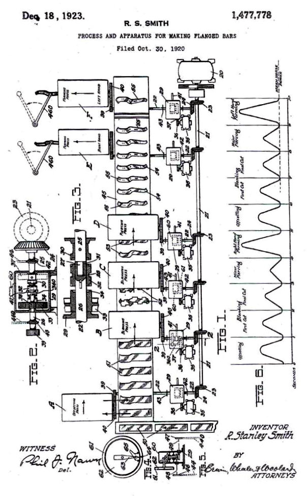
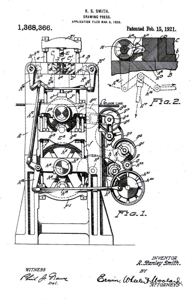
The original patent included 84 pages and 135 individual claims. Subsequent to the original patent, Reuben filed 27 additional patents from the years 1918 through 1922 for machines and processes used to expand and/or complement the original concept. Contrary to the belief the Mechanical Marvel was described in one sole patent, it was the ancillary patents that followed which gave life to the automated construction assembly line. These included patents for self anchoring rivets, piercing presses, intermittently operating motor systems, punch presses, machines for pickling metal plates, drawing presses (for sidebars, crossbars, and flanged bars), etc. (See Family Legacy Timeline, Reuben Stanley Smith Patents, 1948). In 1920, Reuben filed and received a patent which sub-divided operations to make flanged bars. The synchronous manufacturing of flanged bars with the time-cycle of the original Mechanical Marvel was an important design consideration to insure an uninterrupted and continuous manufacturing operation. This was patent 1,477,778 issued on December 18, 1923, for a “Process and Apparatus for Making Flanged Bars.”
Focus on Complete Synchronism
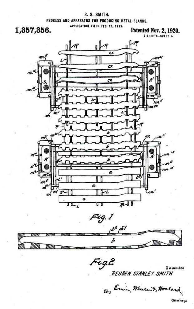
In the body of another patent filed on February 18, 1919, and issued on November 2, 1920, as patent number 1,357,356 for a “Process and Apparatus for Producing Metal Blanks”, Reuben’s verbiage in the patent describes the importance of complete synchronism. He states “In practice, the assemblage referred to is operated in cycles of time, which are sub-divided into alternate periods of work and periods of rest. During the periods in which the work is being performed, the machines of the assemblage operate in substantial synchronism. During periods of rest, the conveyer mechanisms act to transfer the materials being operated upon from department to department, or from machine to machine at such departments as require more than one machine for the completion of the duties to be performed thereat. The assemblage as an entirety is operated upon a schedule which contemplates the production of completed automobile frames in a definite ratio of a given number of frames per minute.” This one paragraph perhaps epitomizes the concept of the complete Mechanical Marvel.

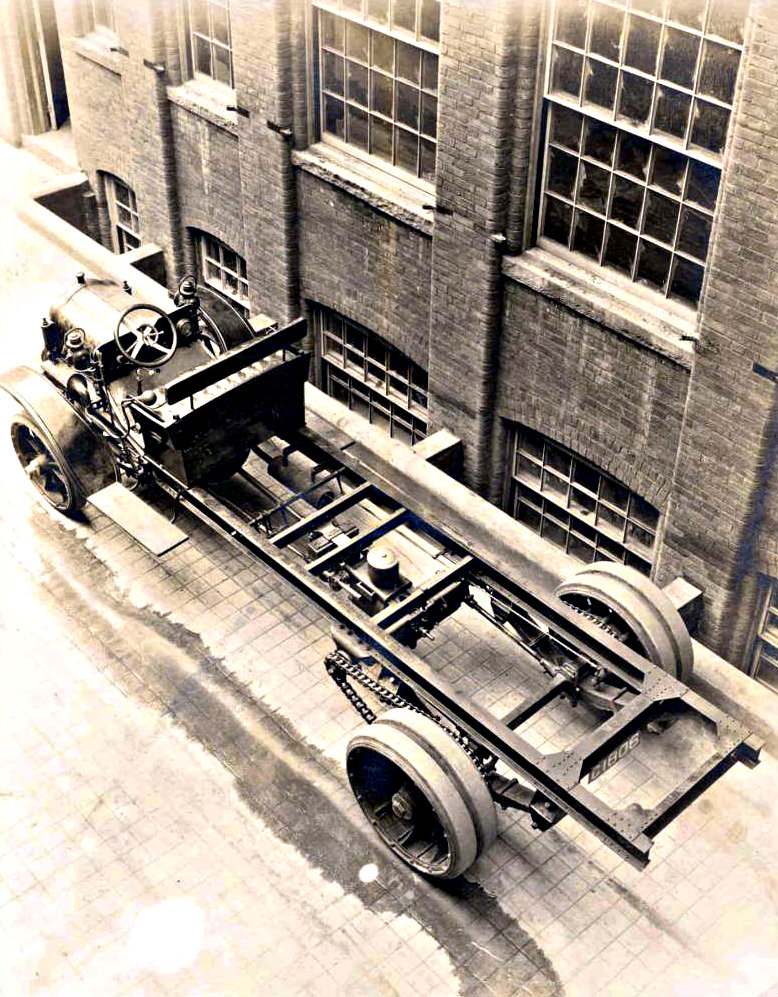
The Frame
While Reuben and his staff were concentrating on the design of a completely synchronized assemblage of machines to produce automobile and truck frames, once constructed and various trial production runs were complete, it became clear the frame itself must be patented. On September 12, 1921, Reuben filed a patent for the “Automobile Frame and Pressed Steel Constructional Elements Therefore.” The issue date was November 13, 1923, for patent number 1,473,651.
What the Mechanical Marvel Could Do
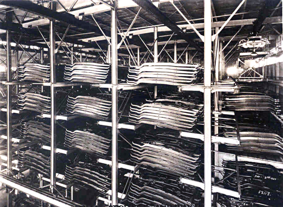
By the spring of 1921, the Mechanical Marvel was ready for operation. It was capable of manufacturing 10,000 frames per day. Each frame required 552 separate operations and in an average day the Mechanical Marvel exceeded 4 million operations. Every eight seconds a completed frame went to storage or into a railcar for delivery to the automakers. This historic assemblage of machines and processes required 180 men to operate it. In contrast, before the Mechanical Marvel was put into operation the Company could produce 3,000 frames per day with 2,000 operators.
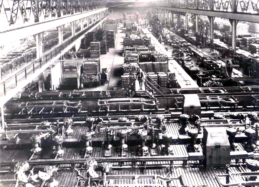
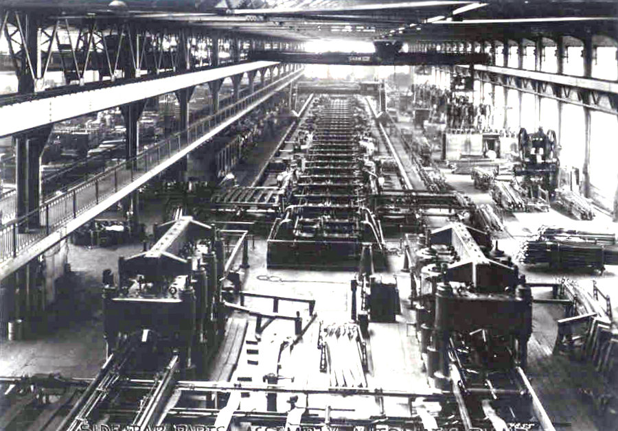
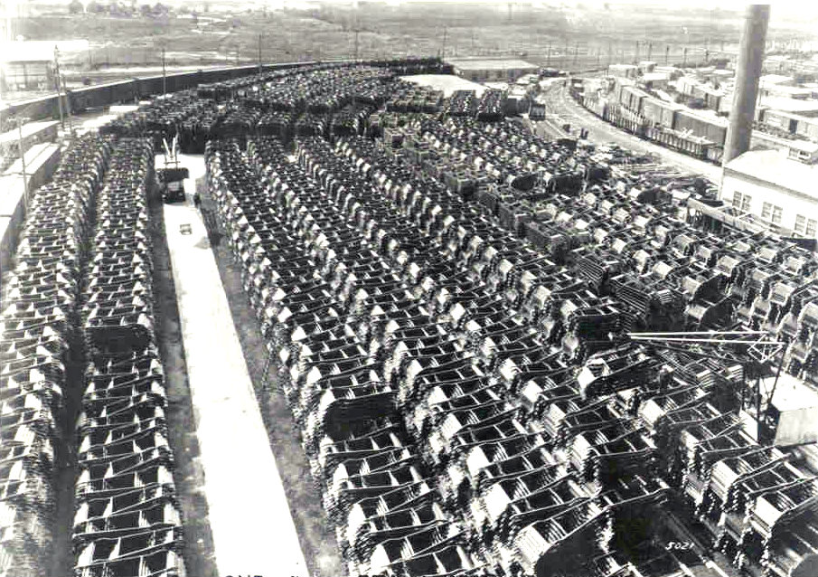
The Mechanical Marvel manufactured frames for 37 years until further welding advances in frame making mandated retirement on June 24, 1958. By 1978, the A.O. Smith Automotive Division had supplied in excess of 93 million passenger car frames and over 33 million truck frames. The Mechanical Marvel received recognition by the ASME as a National Historic Mechanical Engineering Landmark in 1979.

Side Note
Reuben Stanley Smith preferred to go by the name “Stan.” His friends and family members referred to him as either Stan or Stanley. Stan’s many early patents refer to the inventor as R. S. Smith. It wasn’t until much later that the U.S. Patent Office required the full legal name of an inventor on issued patents.
_______________
Additional Brief Notes Regarding the Design of the Mechanical Marvel
Reuben Stanley Smith made it very clear with language used in the original Mechanical Marvel patent, 1,397,020, that the claims made involved a method and apparatus for forming and assembling metal elements. He also made it clear that machines and processes mentioned in the claims would be given separate and distinct mention in other patents to be filed, ancillary to the original patent.
Due to the complexity of the Mechanical Marvel, to organize the structure for descriptive purposes, Stan compartmentalized stages of production into eight departments, calling them Departments A, B, C, D, E, F, G, and H. Within each of those departments, he categorized sub-departments as a, a’, a”, b, b’, b”, c, c’, c”, and so forth. Ancillary patents were subsequently filed for machines used in the sub-departments which fed finished frame elements back to the main line of the Mechanical Marvel once complete. As an example, sub-department (a) may perform an operation then send the element to sub-department (a’) for a different operation, eventually transferring the element to (a”) for a third operation, before sending it back to the main line for assembly.
Department A involved strip feeding and blank forming operations. It also involved the transfer hoist and main piercing line conveyor.
Department B involved the piercing operations. These were holes pierced into metal elements for eventual rivet insertion. Patent 1,397,020 goes into some detail regarding the piercing machines, structure, and arrangement. Department B also involved the doweling and shifting operations which was a means for shifting jigs and track sections from one trackway to another in the piercing department. Transferring metal blanks into the next department is also described.
Department C involved the press feeders and forming presses.
Department D was where the bracket connecting operations were performed.
Department E was for end finishing operations. This is where the hanger feeding and placing mechanism was used as well as heading some of the self anchoring rivets that had already been installed in the hangers (rivets were self-anchoring, Patent 1,457,008 filed October 20, 1919). Malleable rivets were used so it was not required that they be heated before the heading process was introduced.
Department F was simply called “auxiliary.” The machines in this department were similar to those in Departments B and D, whereby in case the number of machines in those departments was inadequate or in case any of the machines in those departments became inoperative, the side bar elements could be transferred through Department F.
Department G housed the assembly conveyor and transferring mechanism.
Department H was where the metal elements were clamped in assembled-relation on the jigs so that the elements were bound together, advanced for reaming operations, then riveting operations. This is where the infamous rivet heading machines were located and a complete frame was born.
Sub-department (a) was for cross bar forming. Sub-department (b) was for cross bar piercing. Sub-department (c) involved cross bar shaping. Sub-department (d) was for cross bar lapping. Sub-department (e) was for cross bar gusset assembly. Sub-department (f) is where the cross bar brackets were assembled. Sub-department (g) involved the assembly conveyor and transferring mechanism. Sub-department (h) was where the metal elements were clamped in relation onto jigs. This also involved a jig advancing mechanism, reaming operations and rivet inserting operations with rivet heading. Most of the machines used in the sub-departments were patented along with the process in the sub-departments (See Family Legacy Timeline, Reuben Stanley Smith patents, year 1948).
Synchronism was accomplished by using three different methods as described in the original Mechanical Marvel patent in quite some detail as well as two designs for Intermittingly Operating Motor Systems (Patent 1,450,330 filed August 4, 1919, and Patent 1,450,340 filed October 20, 1919. See Family Legacy Timeline, Reuben Stanley Smith patents, year 1948). Stanley states “…embodied in an assemblage constituted of a plurality of lines of machines with a plurality of groups of motors for operating the machines of each line independently, intermittingly and alternately, with relation to the other line, and to the said application reference may be had for information as to some of the proposed uses of such assemblage. The present application comprises matter divided out from the application above referred to.” The application Stan refers to is the patent application for the original Mechanical Marvel, 1,397,020. This is one of many references to the original Mechanical Marvel patent described in ancillary patents filed afterwards.

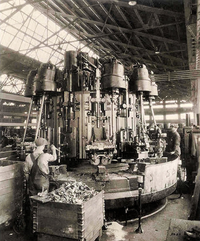
One of the most interesting machines designed by Reuben Stanley Smith is what he called a turret, now commonly referred to as a carousel. Cross bar blanks or other metal elements in various stages of their completion were diverted from the straight line of the Mechanical Marvel so they could be treated by several machines and tools which are associated with the revolving turret. This allowed for a more compact arrangement of machines instead of a linear layout that would take-up more floor space. In the body of the patent, Stan made it clear that the turret did not have to work in synchronism as did other machines in the sub-departments and that various types of machines could be utilized on the turret. The patent describes the turret as an apparatus for forming elements but does not specifically describe the types of machines that could be installed on the turret. One such application for the turret concept was the spring hangar finishing machine.
So much more was involved in the operation and design of the Mechanical Marvel: Special circular switches were developed to aid in the synchronism duty-cycle; electro-magnetism was employed in the metal element clamping system, an ingenious flexible die system (patent 1,470,399) was used to conform to various metal element shapes to prevent die breakage and streamline the retooling process; special dies for the drawing presses (patent 1,475,355) were developed; a process and apparatus for locally annealing metal plates (patent 1,446,356) was introduced along with a magnetic feeding device for the blanking presses (patent 1,343,648); a tension indicator for the drawing presses (patent 1,417,579); an electromagnetic device for serving rivets to nailing machines (patent 1,441,250), and more…much more.
Engineers working directly with Reuben Stanley Smith included Richard Stresau, James Adams Jr., Henry Miller, Edward W. Burgess, Birger T. Andren, Thorvald Hansen, and Frederick Orton.
It can truly be said that the design, development, and assemblage of machines to produce automobile and truck frames, along with the vision, courage, and investment to make them, was indeed a marvel of its time.

Website article author: Walter W. Smith
Website article editor: Paulina Alfaro